Decided to measure the LRCK line again to see if the waveform was cleaner.
The picture speaks for itself. See the trace before here.
Wednesday, December 30, 2009

Reducing sources for noise
Elsewhere it has been measured that the DC-DC converters are a potential source for noise. Because I am not using the headphone output, I decided to cut the traces to these DC-DC converters. It is only required to cut two traces which you can later jumper if you decide to reverse the changes.

Power to the second DC-DC converter goes through a trace on the underside of the board

If you are using a different Musiland model, the traces will be in different places. But the procedure is as follows:
1- Identify the DC-DC converters. These are the 8-pin chips marked "3063". You can find the datasheet for these DC-DC converters here. (There are two of them).
2- Identify the Vcc pin:


3- Find the trace that feeds this line and cut. This line also connects a local resistor and capacitors for the DC-DC converter. It may not matter whether you cut before the local cap or after the local cap, but in my mod I cut it before the local cap.
4- Make sure you don't cut the line in a place that feeds the other linear regulators (there are two other linear regulator that feeds off the same lines - there are several traces but they all connect to the 5V USB power). In the second picture you can see the line (next to the crystal) that feeds both the DC-DC regulator and the linear regulator. It branches off and feeds the DC-DC regulator through a bridge underneath the board.
5- If you plan well, you can actually use external wiring and a switch to reconnect the traces. This will re-enable the local analog output in case you feel like using the built-in headphone amp.
Thursday, December 10, 2009
MUSILAND SPDIF to OPUS DAC (WM8804/WM8741)
Because the MCK for the Musiland devices is 128fs which is "not supported" by the WM8741 DAC (see previous post), I decided to use the SPDIF output of the Musiland to the TwistedPearAudio Wolfson WM8804 spdif receiver board and then to the WM8471 DAC board. With this configuration each component is working at its optimal range. 44.1KHz material goes to the DAC as 44.1KHz material and the DAC can apply high up-sampling allowing it work at its optimal range.

The Musiland 01-MINI has SPDIF out, but it is not connected to an output plug. However, all you have to do is install a resistor and connect the cable to the back side of the board.
Install resistor in R22 position as shown in picture

Connect cable to backside of board

NOTE: I use 221 ohm - in theory, this resistor is a voltage divider with the input 75 ohm resistor you find in spdif receivers in order to bring the level down to .5v-1v or so for "consumer spdif". I also didn't bother with impedance matching, transformer isolation and other "audiophile" concerns as the spdif wire is just a few inches long. I did use a coax that I scavenged from a cheap RCA interconnect cable
Some traces of the spdif signal here. (Monitor US 02, but the chips are the same as the mini)
Musiland I2S Connection to WM8741 DAC
From the MCK compatibility chart we can see that for 44.1 KHz sample rate, 128fs is not supported in the Wolfson WM8741. But I wanted to try it anyway. (Recall that the Musiland output MCK is at 128fs)
It actually works and sounds well. However, when switching through the different internal upsampling options, only medium upsampling and no upsampling work. High upsampling does not work.
This means that the DAC is not working optimally. Perhaps using spdif rather than I2S is a better option for this DAC (Notice from the table that the BB DACs support 128fs with all sampling frequencies)

Monday, December 7, 2009
Master Clock Compatibility

Saturday, December 5, 2009
Measuring BCK (Bit clock)

So far we've measured two out of the 4 lines when using I2S. Strictly speaking, I2S only has 3 lines, but the Master Clock line is required by the DAC and some component generates the master clock.
So we've measured MCK, LRCK and now we measure BCK. The data line cannot be measured because it varies with the data and it is a bit pattern corresponding to the data. So with these 3 measurements, we can characterized the I2S interface.
For 44.1KHz material, we measured 2.8236 MHz. What does this mean? 28236/441=64.0. The BCK is running at 64 times the sampling rate or 64fs. This means that the device sends 32-bit words per channel (yes 32 bits of data per channel).
BCK can be 32fs (16 bit -16-bitx2), 48fs (24-bit per channel) or 64fs (32-bit per channel as it is in our case). DACs data sheet specify the word length it can accept, but since the send and receive bit depth do not have to match, words are either padded or truncated if there is a mismatch.
From Wikipedia:
If the Transmitter is sending 32 bits per channel to a device with only 24 bits of internal precision, the Receiver may simply ignore the extra bits of precision by not storing the bits past the 24th bit. Likewise, if the Transmitter is sending 16 bits per channel to a Receiving device with 24 bits of precision, the receiver will simply Zero-fill the missing bits. This feature makes it possible to mix and match components of varying precision without reconfiguration.This is possible because data is transmitted MSB first.
Measuring Master Clock and fs
Here is another way to measure frequency > 100 KHz. The 40-buck scope has a frequency feature that is good up to 5 MHz (It is probably good up to 8 MHz as some users have experienced)
The picture shows the MCK line with 44.1KHz material playing. If we divide this by the sample rate, 5,647,218 Hz / 44,100 Hz = 128.055. Thus the system is running at 128x fs

What would be the frequency for 48KHz? We know the fs=128x, so the frequency is 48,000x128=6.144 MHz

Pretty good measurement...
Measuring MCK (System or Master Clock)
Another signal line that is required when using the I2S connection is the system clock (MCK or SCK). This runs in the many MHz range so you need a "real" scope. Another diyer, jkenny, took these measurements of his Musiland 01-US. The system clock is the clock that is fed to the DAC and all other signals are based of this clock signal
The picture below is for input signal with 44.1KHz sample rate. If one divides the frequency by the sample rate, 5.71Mhz/44.1Khz=129. System clocks are designed at 128x, 256x, and so on. Thus from this measurement we find that the Musiland device is running its master clock at 128fs
Why is this important? Because DACs are designed to run at a specific range (range of fs) for the master clock. If you operate the DAC outside this range, the DAC performance may suffer

The following picture is for input sample rate of 96KHz

Friday, December 4, 2009
Musiland I2S
One of the reasons I had to measure the I2S frequency was because I connected the MUSILAND 01-MINI to the WM8741 DAC by tapping the I2S lines. Here you can see the MUSILAND device (which implements asynchronous USB transfer and supports up to 192 KHz sample rate content -and good reviews in the audio forums). I took it out of its metal casing, attached it to a plastic board and tapped the I2S lines that connects the fpga to the internal DAC


I2S lines in the Musiland 01-MINI

The I2S lines on the Musiland 01-US


I2S lines in the Musiland 01-MINI

The I2S lines on the Musiland 01-US

Thursday, December 3, 2009
Measuring I2S with Cheap Scope
I decided to to some audio measurement with the scope. Measuring I2S was the perfect exercise as the different clocks are sent in separate wire. Because of the limited bandwidth of the scope, choosing the slowest clock was necessary. A quick look at the I2S specification indicated that measuring the LRCK, the clock that tells you left channel data and right channel data was the line to measure.
Because in a single cycle LRCK indicates the transfer of data for a single stereo sample (left channel and right channel), LRCK always matches the sample rate. See Wikipedea for a better explanation.
Here is the measurement when iTunes plays at 44.1KHz sample rate

Here is the measurement when iTunes plays at 88.2KHz sample rate

Here is the measurement when iTunes plays at 96KHz sample rate

$49 Oscilloscope

A pretty good scope for audio applications. Maximum analog bandwidth is 1 MHz. However, the maximum signal you can comfortably measure is 1/10 of that or 100 KHz (this is a rule of thumb, but I don't know the theory behind it). According to this thread and this thread, the practical upper limit is about 100KHz and with some tweaks and a proper probe you can measure up to 150KHz-200KHz.
There is a Google group with discussions on this scope. Check out the "pages" section for more info on modding/upgrading the scope. The manual can be found here.
Tips & Tricks:
- 10x diy probe: link
Thursday, November 19, 2009
OSR bits in WM8741

According to a Wolfson Engineer,
OSR, it's the DAC-to-input-rate-ratio. We want that to be high to have the DAC run fast, but not too fast to introduce timing related mayhem. You can't set this ratio directly but only indirectly through R7.Thus the OSR bits in the DAC controls the Internal upsampling of the DAC.
When you set low rate what you tell the DSP is high OSR. It means we use the maximum amount of upsampling since we know the input rate is low enough such that the resulting DAC frequency lies in the sweet spot of performance: high to run the sigma/delta with loads of headroom, not too high so as to introduce analogue problems.
For medium and high rates, the actual upsampling ratio reduces such that with the higher input rates we end up with the same actual DAC frequency.
- Low rate means "apply highest internal upsampling"
- Medium rate means "apply medium internal upsampling"
- High rate means "do not apply any internal upsampling"
- If you input sample frequency to the DAC is 44.1 KHz, you can select any one of the 3 settings. With Low Rate, maximum internal upsampling is applied, with High Rate, no internal upsampling will be applied.
- If your input sample frequency to the DAC is 192 KHz, then you can only select High Rate, meaning that no internal upsampling can be applied because the input data is at high rate or has been upsampled outside of the DAC
Wednesday, November 18, 2009
Testing WM8741 filter setting
Some people can hear differences between the digital filters in the WM8741 DAC. In my setup, I can't really hear clear differences between the different filter settings, and up to now I had no way to test whether the different filters were being selected by the software in Arduino.
The good people at AMB did an excellent job in characterizing filters 1, 2, and 3 with different upsampling, and found that without upsampling (i.e., with 44.1KHz material), filters 1 and 2 will roll off at 15Khz as compared with filter 3 as shown in this picture:

I downloaded a 15 KHz test tone (from mosquito ringtones) and played it in a loop in iTunes. The output was set at 44.1 KHz and I set the OSR bit in the WM8741 to "high" (meaning do not use internal upsampling). Then I selected and compared filters 1, 2, 3. Indeed, you can hear an attenuation with filters 1 and 2 as compared to filter 3. Filter 1 is filter A, 2 is B and 3 is C.
Therefore the software is working. (Keep in mind that if you are an old guy, you will need to ask a kid to help you listen to the 15KHz test tone)
Tuesday, November 3, 2009
Logic Level Converter

NKC Electronics has released this little board to allow converting voltage levels between Arduino and other devices.
Recall that Arduino is typically a 5V device and devices that you want to control (such as a DAC) are 3V devices. If you use the Arduino I2C interface (which is 5V logic) to control the 3V I2C interface of a device, you need this converter. More information here.
Thursday, October 15, 2009
LCDUINO-1

When I started my project, I posted in DIYAudio and got totally ignored. Fortunately other people recognized the potential of using Arduino for audio and have invested in making Arduino an "audio-friendly" device.
LCDUINO is an arduino-compatible board (I wouldn't call it a clone because it cannot use "arduino shields"). I believe the primary goal was to build a board of the same footprint as a 16x2 LCD so that it fits neatly behind the LCD, facilitating the construction of something like a headphone amplifier.
The device is the equivalent of an Arduino board (or clone) plus a serial LCD (which is what I used for my project). LCDUINO adds a real time clock, but lacks the USB chip for programming. I think a second goal for the project was to provide a lot of code so that for many purposes, no programming is necessary. If you want to program the board yourself, you will need to purchase a USB to serial converter and connect it to the LCDUINO
The real jewel in LCDUINO is the code that linuxworks is developing for the board which will be available to the user community.
You can find more at linuxworks web site and the AMB website.
Arduino+Buffalo
I think this is the first public project of Arduino controlling a Twistedpairaudio Buffalo DAC [link]


Thursday, October 8, 2009
Tuning iTunes
Haven't posted for a while... Spending time listening to music. I use iTunes running on Windows Vista
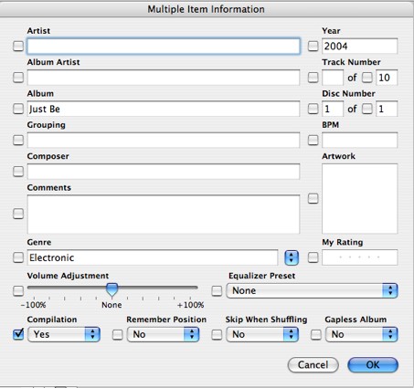
One anoying thing in iTunes is that in album view, it separates songs if they have multiple artists. The way to fix this is the following:
"You can mark these songs as a compilation in iTunes. Do do this, select all the songs that you want to be included in the compilation and select Get Info from the file menu and select Yes in the Compilation menu as shown below. After clicking OK iTunes group all the selected songs together." [Link to Apple for complete article]
iTunes on PCs is also bit perfect if you match the sampling rate in the Quicktime control panel to the sampling rate of the source material. Ken Poon explains it well in his blog.
The latest version of iTunes has a different dialog box:

Tuesday, August 4, 2009
4 1/4 Digit DMM

Purchased this DMM in Shenzhen, China for RMB 200 (about 30 bucks) at the famous SEG Electronics Market. Yeap, everything you've heard about this place is true!.
Sunday, June 28, 2009

Friday, June 26, 2009
How Asynchronous Rate Conversion Works
Continuing with the discussion thread at DIYaudio, I will attempt to summarize how ASRC works.
Synchronous rate conversion
Let's say we are dealing with a SYNCHRONOUS rate conversion problem, from 44.1kHz to 48kHz, where both rates are derived from the SAME clock source. Meaning that, when measured with the same stopwatch (clock), the 44.1kHz rate is EXACLTY 44.1kHz, and the 48kHz rate is EXACTLY 48kHz. In this environment, one could simply interpolate by 160 to 7.056MHz and decimate by 147 to 48kHz:
The first thing to do (at least conceptually) is to take the 44.1kHz data stream and stuff 160-1=159 zeros, evenly spaced in the time domain, between each sample. Then you apply the "zero-stuffed" sequence to a low-pass filter (cutoff at half the original sample rate or 22.05kHz), which will finalize the interpolation process by "filling in" the zeros with real data points. (hard to envision, but this is what happens with digital filters).
Now we simply grab every 147th sample, to generate our output sequence at 48kHz. That "grabbing every 147th sample" is precisely DECIMATION. Just digital re-sampling, or down-sampling. We didn't need a special filter for decimation in this case, because the interpolation filter did it's job for us.
Asynchronous rate conversion
In ASYNCHRONOUS sample rate conversion. The 44.1kHz clock and the 48kHz are NOT derived from the same time base, meaning they are not exactly the numbers they claim to be, when measured with the same stopwatch. So, in this asynchronous world, if have two time lines: one with ticks every 44.1kHz, the other one with ticks every 48kHz. Thus by definition, Asynchronous Rate Conversion is this:
Asynchronous Sample Rate Conversion: How does it work
Here we have a situation where we need to digitally CALCULATE output data samples at new points in time, different than the input data time points. And the time points are NOT synchronized. ... so there is no finite integer interpolation that we can perform on the input data that will align PERFECTLY with the output time points we need.
But we don’t have to be PERFECT. Conceptually, we will interpolate the input data by a pretty huge number, in fact, by a pretty huge INTEGER number, so that we effectively "fill in" very many samples in-between the original Fs_in samples. So instead of providing an interpolated input sample that corresponds to that exact point in time, we can provide the closest (in time) interpolated sample that is calculated. How BIG will the error be? The question is therefore is ... How far do I have to interpolate, by what integer, so that grabbing the most recent sample will give me acceptably LOW error ?
We can never achieve perfection here, but we can get ARBITRARILY CLOSE ... simply because the higher I interpolate, the lower the error. So the question is, how big should the interpolation number “N” be?
After a lot of math, it can be shown that input data at the Fs_in rate needs to be interpolated by N~2^20 (1,048,576 -over a million!), so that the error incurred by Asynchronous decimation to Fs_out will be acceptably small. But 2^20 is HUGE resulting in a frequency of 50 GHz and this is for an input sample frequency of 44.1 KHz.
Fortunately, because most of the samples are going to be ignored when decimating to the output sample rate (e.g. 48 KHz), we don’t have to calculate them in the first place. We only need the samples closest to the output sample rate. In order to do this we use FIR filters (Finite Impulse Response). And though clever implementation, and by knowing the output sample rate, the computational demands of implementing the FIR filter are manageable in a typical commercial implementation. (Meaning you don't have to do all the math or have heavy-duty computational engines).
My observations: Rate conversion from 44.1KHz to 192KHz is the same as 44.1 KHz to 176.4 KHz
From the above discussion, it can be seen that because the system is designed to select the interpolated sample that is closest to the output sampling rate, it does not matter whether the output sample rate is an integer multiple of the original sample rate or not.
This is important because in some audio circles it is believed that for CD material with its native sample frequency of 44.1KHz, it would "sounds better" if sample-rate converted to 88.2 KHz or 176.4KHz (integer multiple) than to 96KHz or 192KHz (not integer multiple). The argument presented here (by the expert at DIYaudio), at least from a theoretical point of view implies that the closest matching sample to clock-ticks in a 192 KHz clock, for example, should be no worse than the closest matching sample to clock-ticks in a 176.4 KHz clock.
Synchronous rate conversion
Let's say we are dealing with a SYNCHRONOUS rate conversion problem, from 44.1kHz to 48kHz, where both rates are derived from the SAME clock source. Meaning that, when measured with the same stopwatch (clock), the 44.1kHz rate is EXACLTY 44.1kHz, and the 48kHz rate is EXACTLY 48kHz. In this environment, one could simply interpolate by 160 to 7.056MHz and decimate by 147 to 48kHz:
The first thing to do (at least conceptually) is to take the 44.1kHz data stream and stuff 160-1=159 zeros, evenly spaced in the time domain, between each sample. Then you apply the "zero-stuffed" sequence to a low-pass filter (cutoff at half the original sample rate or 22.05kHz), which will finalize the interpolation process by "filling in" the zeros with real data points. (hard to envision, but this is what happens with digital filters).
Now we simply grab every 147th sample, to generate our output sequence at 48kHz. That "grabbing every 147th sample" is precisely DECIMATION. Just digital re-sampling, or down-sampling. We didn't need a special filter for decimation in this case, because the interpolation filter did it's job for us.
Asynchronous rate conversion
In ASYNCHRONOUS sample rate conversion. The 44.1kHz clock and the 48kHz are NOT derived from the same time base, meaning they are not exactly the numbers they claim to be, when measured with the same stopwatch. So, in this asynchronous world, if have two time lines: one with ticks every 44.1kHz, the other one with ticks every 48kHz. Thus by definition, Asynchronous Rate Conversion is this:
There is NO interpolation by any FINITE integer you can do on the INPUT sample points ... meaning, no finite number of samples you can evenly space between the original samples ... that will give you perfect alignment with all the OUTPUT sample points.
Asynchronous Sample Rate Conversion: How does it work
Here we have a situation where we need to digitally CALCULATE output data samples at new points in time, different than the input data time points. And the time points are NOT synchronized. ... so there is no finite integer interpolation that we can perform on the input data that will align PERFECTLY with the output time points we need.
But we don’t have to be PERFECT. Conceptually, we will interpolate the input data by a pretty huge number, in fact, by a pretty huge INTEGER number, so that we effectively "fill in" very many samples in-between the original Fs_in samples. So instead of providing an interpolated input sample that corresponds to that exact point in time, we can provide the closest (in time) interpolated sample that is calculated. How BIG will the error be? The question is therefore is ... How far do I have to interpolate, by what integer, so that grabbing the most recent sample will give me acceptably LOW error ?
We can never achieve perfection here, but we can get ARBITRARILY CLOSE ... simply because the higher I interpolate, the lower the error. So the question is, how big should the interpolation number “N” be?
After a lot of math, it can be shown that input data at the Fs_in rate needs to be interpolated by N~2^20 (1,048,576 -over a million!), so that the error incurred by Asynchronous decimation to Fs_out will be acceptably small. But 2^20 is HUGE resulting in a frequency of 50 GHz and this is for an input sample frequency of 44.1 KHz.
Fortunately, because most of the samples are going to be ignored when decimating to the output sample rate (e.g. 48 KHz), we don’t have to calculate them in the first place. We only need the samples closest to the output sample rate. In order to do this we use FIR filters (Finite Impulse Response). And though clever implementation, and by knowing the output sample rate, the computational demands of implementing the FIR filter are manageable in a typical commercial implementation. (Meaning you don't have to do all the math or have heavy-duty computational engines).
My observations: Rate conversion from 44.1KHz to 192KHz is the same as 44.1 KHz to 176.4 KHz
From the above discussion, it can be seen that because the system is designed to select the interpolated sample that is closest to the output sampling rate, it does not matter whether the output sample rate is an integer multiple of the original sample rate or not.
This is important because in some audio circles it is believed that for CD material with its native sample frequency of 44.1KHz, it would "sounds better" if sample-rate converted to 88.2 KHz or 176.4KHz (integer multiple) than to 96KHz or 192KHz (not integer multiple). The argument presented here (by the expert at DIYaudio), at least from a theoretical point of view implies that the closest matching sample to clock-ticks in a 192 KHz clock, for example, should be no worse than the closest matching sample to clock-ticks in a 176.4 KHz clock.
Thursday, June 25, 2009
Asynchronous Re-clocker vs Asynchronous Rate Converter
The same discussion thread teaches the theory behind sample rate conversion.
We should first distinguish between two terms that are often used interchangeably in audio circles but are completely different technologies:
Asynchronous re-clocking
Asynchronous Sample Rate Conversion:
We should first distinguish between two terms that are often used interchangeably in audio circles but are completely different technologies:
Asynchronous re-clocking
Asynchronous re-clocking or re-sampling: this term describes a pretty simple operation where a digital audio signal is simply re-clocked by a clock from a different time base. There is no interpolation or rate conversion performed on the signal.
Asynchronous Sample Rate Conversion:
This is categorically different, in the sense that SIGNIFICANT interpolation is performed on the Fs_in (input sample rate) signal to minimize error (both time & freq domain) when the ultimate decimation to Fs_out (output sample rate) occurs. Example chips that can perform this function are the CS8420, AD1896 (and their brethren)...
...and the SRC4192 which is the subject of the next project.
More on Pre/Post ringing
There is an excellent discussion thread on digital sampling at DIYAudio. In one of the posts, the following is explained:
What is described above is the fact that with a linear phase filter, reducing the ringing will require the use of slow roll off filters allowing higher frequency images to reflect back into the audio band (this is called Aliasing).
More modern DACs such as the one we used in this project are addressing this problem with so called "minimum phase filters" and to completely eliminate any aliasing, the concept of "Apodizing filters" are used together with minimum phase filters.
We previously explained the digital filters of the WM8741 here.
"Pre/post ringing : most obvious in the classic step response of a steep, linear phase (usually FIR) filter. ... Let me just say now, for the record, that the pre/post ringing we often encounter in digital audio is nothing more than an artifact of the Gibbs phenomenon which simply states that abrupt transitions or discontinuities in one domain, cause ringing in the other.
Band-limited systems unfortunately fit in this category and there is no better example of a SHARPLY band-limited system than digital audio. Don't like the ringing? Sure we can eliminate it but the price you pay will be aliasing, pure & simple, no way around it. And that's a BAD tradeoff."
What is described above is the fact that with a linear phase filter, reducing the ringing will require the use of slow roll off filters allowing higher frequency images to reflect back into the audio band (this is called Aliasing).
More modern DACs such as the one we used in this project are addressing this problem with so called "minimum phase filters" and to completely eliminate any aliasing, the concept of "Apodizing filters" are used together with minimum phase filters.
We previously explained the digital filters of the WM8741 here.
Wednesday, June 24, 2009
Which I/O Expander?
My next project is to control the Texas Instruments SRC4192 chip. This device is an "asynchronous reclocker" and feeds the DAC. Theoretically it reduces jitter because it recreates the clock with a much better on-board oscillator. The device is implemented in a kit board from TwistedPearAudio.
The block diagram is as follows:

In order to interface to the control logic lines, I would need an I/O expander that would communicate with Arduino. Basically you want to swith these lines high or low to select the different configurations and features of the device.
Since there are up to 15 control lines and it needs to support the I2C protocol (to communicate with Arduino) and must by in DIP package (for easy soldering). I would need a 16-port I/O expander in DIP package. Looking over at Digikey, there is just one device in stock that meets the criteria: the PCA9555 by NXP Semiconductors.
It cost $2.13 Application note AN469 explains how these devices work in great detail.
More on Volume
In the latest code, I've fixed the volume values I used to program the WM8741. Previously I mistakenly used 0.25 dB as the smallest interval whereas it is .125 dB the smallest interval, so my volume readings were twice the actual value.
Also I did not see the need to use an interval of less than 1 dB because it is already not very discernible a difference of 1 dB.
Now, the typical listening level is above -50 dB, and mostly in the -30 dB to -15 dB. Therefore above the -48 dB at which point you will start experiencing (theoretically) some loss in information due to the nature of digital volume control.
I also got a response from Wolfson about how the volume control is implemented: Basically input less than 24 bit is padded to 24 bit, input that is 25 to 32 bit is reduced to to 24 bit with dither and the volume control is applied at the next stage.
Monday, June 22, 2009
LCD Settings in Arduino EEPROM
I've added adjusting the LCD Brightness and Contrast with the remote. I've assigned one button in the remote to select between "no adjustment", "brightness adjustment" and "contrast adjustment". This button is a toggle between these three modes.

When entering the brightness mode, the current value is read from the Arduino EEPROM. Two other buttons in the remote are used to increase the value and decrease the value, and adjust the LCD accordingly.

When entering the contrast mode, the current value for contrast is read from the Arduino EEPROM. Two other buttons in the remote are used to increase the value and decrease the value, and adjust the LCD accordingly.

When you exit the adjustment mode, the current settings for brightness and contrast are saved in the Arduino EEPROM. I've used addresses 0 and 1 in the EEPROM space to save the two values. The EEPROM of the Arduino ATmega 168 has 512 bytes of space and the ATmega328 has 1 K bytes of space.
The code for selecting the mode, read and write to EEPROM is as follows. Pressing a specified key in the remote will invoke the following code:
To adjust the brightness and contrast, we send a value to a specific address in the LCD I2C interface/controller (This is a I2C LCD from web4robot). We use the Arduino wire library. The I2C address for the LCD is 0x4C, 0xFE is a prefix indicating that it is a command and not text to be displayed. 0x03 is the command for brightness and ox04 is the command for contrast. After sending the prefix and the command, the value is sent. Brightness value is 0-255 and contrast value is 0-100. The code is as follows:

When entering the brightness mode, the current value is read from the Arduino EEPROM. Two other buttons in the remote are used to increase the value and decrease the value, and adjust the LCD accordingly.

When entering the contrast mode, the current value for contrast is read from the Arduino EEPROM. Two other buttons in the remote are used to increase the value and decrease the value, and adjust the LCD accordingly.

When you exit the adjustment mode, the current settings for brightness and contrast are saved in the Arduino EEPROM. I've used addresses 0 and 1 in the EEPROM space to save the two values. The EEPROM of the Arduino ATmega 168 has 512 bytes of space and the ATmega328 has 1 K bytes of space.
The code for selecting the mode, read and write to EEPROM is as follows. Pressing a specified key in the remote will invoke the following code:
case KEYDISPLAY:
   BC++;
   if (BC%3==0){
     lcd.setCursor(0,4);
     lcd.print("       ");
     EEPROM.write(BRIADDR,brightness); // Save value
     EEPROM.write(CONADDR,contrast);  // Save Value
   }
   if (BC%3==1){
     lcd.setCursor(0,4);
     lcd.print("BRI ");
     brightness=EEPROM.read(BRIADDR); // Read value
     lcd.print(brightness);
   }
   if (BC%3==2 ){
     lcd.setCursor(0,4);
     lcd.print("CON    ");
     contrast=EEPROM.read(CONADDR);  // Read value
     lcd.setCursor(8,0);
     lcd.print(contrast);
   }
   delay(100);
   break;
To adjust the brightness and contrast, we send a value to a specific address in the LCD I2C interface/controller (This is a I2C LCD from web4robot). We use the Arduino wire library. The I2C address for the LCD is 0x4C, 0xFE is a prefix indicating that it is a command and not text to be displayed. 0x03 is the command for brightness and ox04 is the command for contrast. After sending the prefix and the command, the value is sent. Brightness value is 0-255 and contrast value is 0-100. The code is as follows:
// Routines for LCD Adjustment

// For LCD backlight adjustment
void BackLight(uint8_t bright)
{
Wire.beginTransmission(0x4C);
Wire.send(0xFE);
Wire.send(0x03);
Wire.send(bright);
Wire.endTransmission();
delay(25);
}

// For LCD contrast adjustment
void Contrast(uint8_t cont)
{
Wire.beginTransmission(0x4C);
Wire.send(0xFE);
Wire.send(0x04);
Wire.send(cont);
Wire.endTransmission();
delay(25);
}
Sunday, June 21, 2009
Latest Code v 0.7
Everything I've written is in this new code base. And everything is less than 9K. Link in the sidebar.
Saturday, June 20, 2009
New Fonts
Inspired by a new 4-line large font template at the Arduino forums (you can find the link in the sidebar), I decided to tweak my own 3-line Arduino large font.
Basically you create a number of shapes as custom characters and used them to form the large font. However, you are limited by the number of custom fonts you can specify in an LCD (typically 8). The 4-line large font in the Arduino forums is actually the same size as my 3-line large font. But by having 4 lines you have more flexibility in positioning the custom characters "to preety-up" the fonts but you give up some speed in displaying the large numbers (25% speed penalty: 3 lines vs 4 lines). Here are the results

The left most number displays the selected digital filter in the DAC. Above, I've added an abbreviation to the name of the filter. In this case, LnS is "Linear Phase, Smooth Roll Off".

"LnA" means "Linear Phase, Apodizing". Also displayed is RATE, the input sample rate to the DAC. There is also filter #2: MnS: "Minimum Phase Smooth Roll-off"

"BrK" means "Brickwall" filter. Also displayed is INPT, the input format to the DAC. The WM8141 can receive both PCM (from CD players) and DSD (from SACD players). In the future i will be experimenting with extracting the DSD signal from inside a player and feeding this signal straight to the DAC.

"MnA" is "Minimum Phase, Apodizing" filter. Here RATE has been changed to 48K. Because the incoming signal is processed through a asynchronous reclocker chip to 192KHz, there is a sample rate mismatch and the DAC does not output any sound (In theory, this setting selects the appropriate filters to match the sample rate). In the future I will be using Arduino to control the asynchronous reclocker chip in order to change its output sample rate.
Saturday, June 13, 2009
I2C Address and R/W bit
I was reviewing my code and could not remember why the register addresses I defined in the code was different from the register addresses defined in the data sheet of the WM8741. After an hour reviewing the data sheet and the I2C protocol, I finaly realized that I2C address are 7 bit and the 8th bit is the Read/Write bit.
Since all the registers of the WM8741 are all write registers (R/W bit=0), they all end with zero. So the address value that you send in the I2C protocol is the 7 bit address plus the R/W bit, so the 8-bit values ends with zero.
Example:
7-bit Address plus R/W bit
00h=0000000 plus R/W bit = 00000000 = 00h or 0x00
01h=0000001 plus R/W bit = 00000010 = 02h or 0x02
02h=0000010 plus R/W bit = 00000100 = 04h or 0x04
Thursday, June 11, 2009
Why Pull-Up Resistor?
An often suggestion in Arduino debugging is "whether or not a pull-up resistor has been installed"
Why do we need a pull-up resistor? This article explains it well (and this one too), but in summary,
But since Arduino has built-in pull-up resistors that can be enabled in software, you should think about a configuration that only requires pull-up resistor or you must implement the pull-down externally. However, if your external signal already has two definite states (high and low), then you don't need to enable the pull-up resistors inside the Atmel chip
Why do we need a pull-up resistor? This article explains it well (and this one too), but in summary,
For an (digital) input pin, A pull-up resistor will set a default value when there is no signal at the input. In other words, when there is no input you don't want some random value but a definite value.Also,
- If when there is input you measure 0 (or low), and when there is no input you want it to measure 1 (or high), then you must use a pull-up resistor.
- If when there is input and you measure 1 (or high), and when there is no input you want it to measure 0 (or low), then you must use a pull-down resistor.
But since Arduino has built-in pull-up resistors that can be enabled in software, you should think about a configuration that only requires pull-up resistor or you must implement the pull-down externally. However, if your external signal already has two definite states (high and low), then you don't need to enable the pull-up resistors inside the Atmel chip
Monday, June 1, 2009
Arduino Code for Rotary Encoder
(Update: I've improved the code. Take a look here. You have the choice to do h/w deboucing or s/w debouncing or both. The s/w debouncing code is just one line of code)
Reliable use of mechanical encoders requires two components: a hardware tweak and (of course) code. Although there are many sample code for rotary encoder, I feel the following is the simplest code for rotary encoders. This version is interrupt-based.
The interrupt routine simply detects direction of motion:
We attach the interrupt with:
During set up, we want to enable the pull-up resistors for pin 2 and pin 4 with:
Then in a loop we detect when the flags are set and do accordingly:
Reliable use of mechanical encoders requires two components: a hardware tweak and (of course) code. Although there are many sample code for rotary encoder, I feel the following is the simplest code for rotary encoders. This version is interrupt-based.
The interrupt routine simply detects direction of motion:
void decoder()Here we connect terminal A of the rotary encoder to Arduino's digital pin 4 and terminal B to digitalpin 2. The third terminal of the encoder is connected to GND. In this configuration the rotary encoder pulses will be pulling the pins to GND. In this example, we are controlling volume so one direction is volume up and the other direction is volume down.
{
if (digitalRead(4) == digitalRead(2))
{
volUp = 1; //if encoder channels are the same, direction is CW
}
else
{
volDown = 1; //if they are not the same, direction is CCW
}
}
We attach the interrupt with:
attachInterrupt(0, decoder, CHANGE);and we detects CHANGE of the pulse. We need to detect rising edge and falling edge of the pulse in order to utilize the full resolution of the rotary encoder.
During set up, we want to enable the pull-up resistors for pin 2 and pin 4 with:
pinMode(VOLUPPIN, INPUT); // Pin 2Note: it doesn't matter which channel is connected to which pin to start with. You can always switch the connections if you expect the opposite result.
digitalWrite(VOLUPPIN, HIGH); // Enable pull-up resistor
pinMode(VOLDOWNPIN, INPUT); // Pin 4
digitalWrite(VOLDOWNPIN, HIGH); // Enable pull-up resistor
Then in a loop we detect when the flags are set and do accordingly:
while(volUp==1) // CW motion in the rotary encoder
{
volUp=0; // Reset the flag
// Do something
}
while(volDown==1) // CCW motion in rotary encoder
{
volDown=0; // clear the flag
// Do something else
}
Sunday, May 31, 2009
Code Explained
Arranged a bit the way I present/share the code. Check out the sidebar links.
Now that I've learned a bit more, I'm going to attempt to explain the code I write, and then present the complete code. Hopefully this will be most useful for beginners.
The code presented in the sidebar is/will be the best and simplest examples I could find, customized to the current application.
Now that I've learned a bit more, I'm going to attempt to explain the code I write, and then present the complete code. Hopefully this will be most useful for beginners.
The code presented in the sidebar is/will be the best and simplest examples I could find, customized to the current application.
Arduino Controller & DAC

The DAC is a kit from TwistedPear Audio, based on the WM8741.
2-wire I2C connection (plus GND)

Inside the OPUS DAC: Leftmost is the toroid transformer inside a tin can. Middle is a dual DC power supply, rightmost are 3 boards stacked: top is the SPDIF receiver, middle is the asynchronous re-sampler and re-clocker board and bottom is the DAC board based on the Wolfson 8741.

Detail of the 2-wire I2C connection to the DAC board.

Detailed connection diagram

Arduino I2C connections are analog pin 4 and 5

Saturday, May 30, 2009
Reusing Hard Disk Parts for the Case

Always wanted to reuse old hard disks as the cases are made of high quality aluminum. Here are parts from different hard disks. These parts will form the top and bottom of the Arduino controller case. Once you get a hold of the right screwdrivers, it is a breeze to dismantle a hard drive (It is actually faster and more fun than reformatting a hard drive if you want to securely dispose of it)

The first step is to cut the front piece. After measuring the text area of the LCD, I cut the opening with a hand saw (and a lot of sanding to get is straight). Then in order to align and mount the LCD I glued two strips of wood with the LCD in place. (Although the picture below shows the sides already glued, you do this step without the sides in place)

Next I cut the sides and glue them to the front piece. In order to facilitate positioning and gluing, I first mounted the top and bottom aluminum pieces to the sides and then with the box already formed, I glued it to the front piece. I also put some weight on top of the box to allow better gluing. Used regular wood glue.

The front and sides glued together.

Next, I mounted the "shield" to the case. In this configuration, the shield is fixed and the Arduino (Freeduino) is removable. All the connections are to the shield, including DC power. I can easily remove the Arduino board for programming and leave the controller attached to the stereo system. The small green board at the forefront is the 3.3V I2C level shifter. The DAC connects to the Arduino controller through these 5 pins. Center pin is GND as GND has to be shared between controller and device.

Below, you can see the Freeduino board mounted on top of the "shield". As the Freeduini is a kit, I soldered the headers on the bottom of the board.

Here you can see detailed connections to the different parts.


Subscribe to:
Posts (Atom)